Front End Engineering & Design (FEED)
Process Simulation (Aspen Plus or Aspen HYSYS)
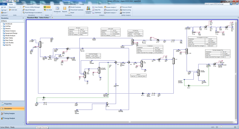
Over the last several decades, the technology of chemical processing has made extensive use of computer simulations to get a detailed and comprehensive understanding of processes. The key to these simulations is the quality of physical properties and attendant thermodynamics. Improvements of these factors now enable significant breakthroughs and increased confidence in using process simulations to generate meaningful data. An example of an Aspen Plus simulation is shown below.
Heat and Material Balance (HMB)
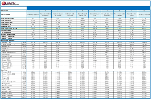
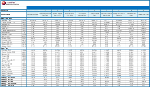
A major outcome of a simulation is to develop the Heat & Material Balances (HMB) wrapped around the process. The HMBs enable the design engineers to understand the thermal and mass transport values at various critical points in the process. An example of an HMB simulation output is shown below.
Process Flow Diagrams
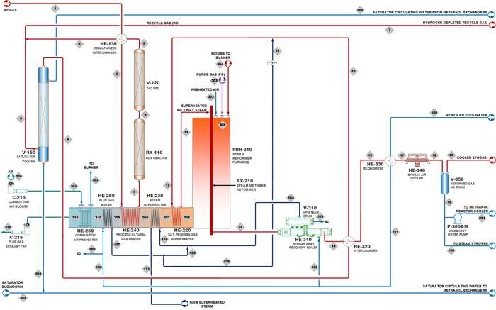
Process Flow Diagrams (PFDs) are a high level depiction of the process based upon the HMB to enable a better understanding of key aspects that are involved. PFDs are used to identify major unit operations and transformation points within the process. An example of a PFD is shown below.
Applicable Codes & Standards
Unitel adheres to the applicable codes and standards noted below. Unitel is well versed with other applicable codes and standards and will conform to these requirements when requested.

Piping and Instrumentation Diagrams
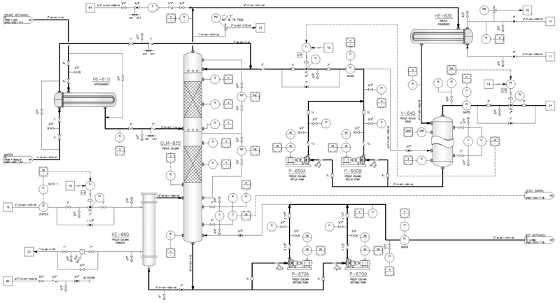
Piping and Instrumentation Diagrams (P&IDs) are an essential component of process design. P&IDs must show all the necessary piping and instrumentation that will be a part of the process. The P&IDs also establish a common protocol for communications between process engineers, piping engineers and instrumentation engineers. An example of a P&ID is shown below.
Utility Diagrams
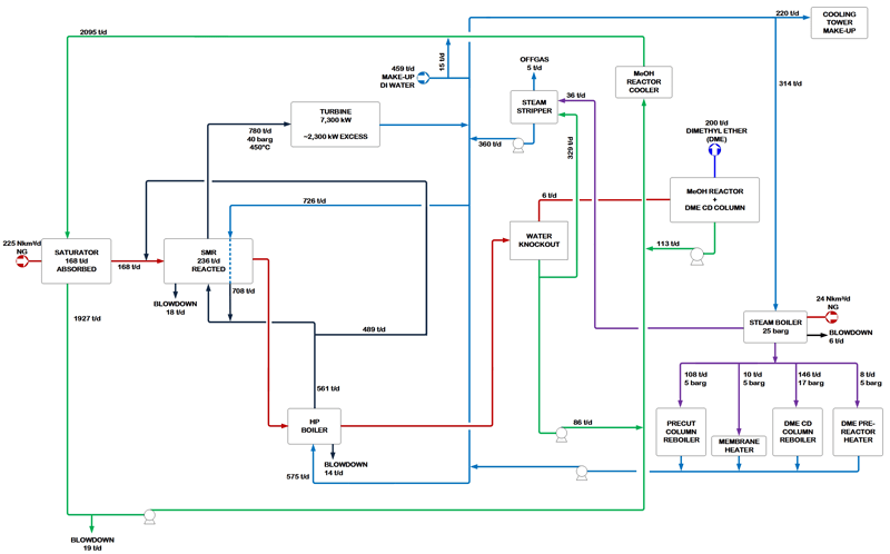
A typical process uses utilities such as water, air and electric power. Water may be used either in the process, or for cooling and/or production of steam. Air may also be used in the process or for instrument applications. Electric power of course is typically used at various points in the process and throughout the site.
It is always useful to develop diagrams that show the flow and utilization of each utility. An example of a water balance/utility diagram is shown below.
Line Sizing/Hydraulics
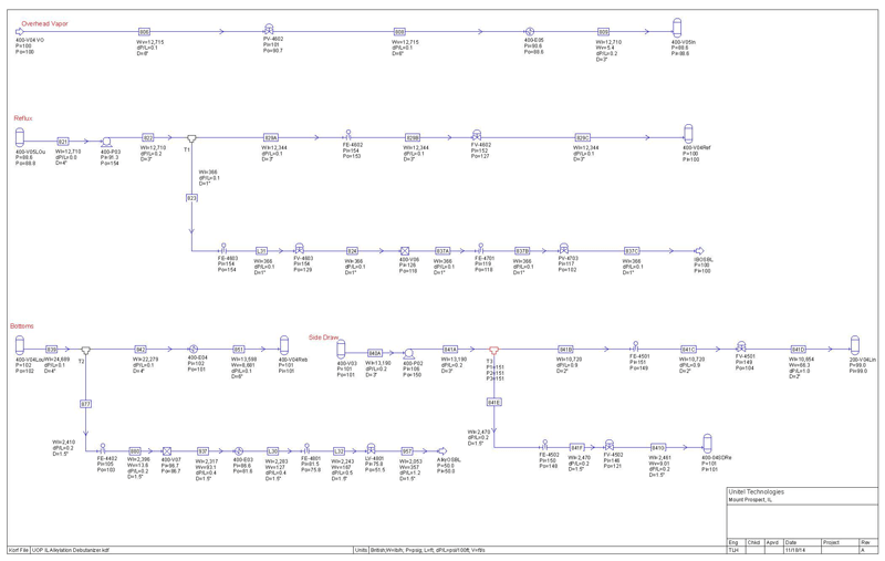
Unitel uses KORF software for conducting hydraulic calculations to determine the optimal line sizes for the gases and liquids flowing in the process. An example of an application is shown below.
Relief Valve Sizing/Flare System Hydraulics
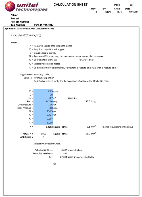
Relief valves are a critical component of a well designed process. Most chemical processes may be subject to pressure and thermal excursions that necessitate an automatic relieving protocol. This relieving is achieved by relief valves at various locations in the process. Each relief valve has to be sized based upon various scenarios that may result in an excursion. It is a systematic process that must also incorporate the results of a Process Hazard Analysis (PHA). In most cases, the relief valves will direct the gases and liquids into a flare system. The hydraulics of the flare system have to be sized to accommodate maximum relieving rates. An example of a relief valve sizing is shown below.
Process Optimization
Value Engineering
The objective of value engineering is as follows: if a client anticipates a research program to be of a short duration, the specifications of equipment and materials of construction may be optimized for that program. If the research program is of a longer duration wherein the pilot plant not only provides process data but also long term product optimization, it may be necessary to utilize a different design basis and materials of construction.
Equipment Specifications
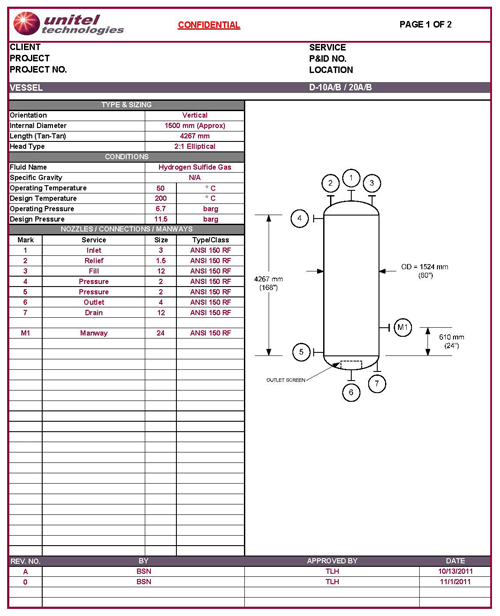
A typical process includes a large number of major equipment items such as pumps, compressors, vessels, reactors, heat exchangers, mass transfer columns, etc. Each one of these pieces of equipment have to be very carefully and diligently specified to accommodate maximum operating conditions. Nozzle locations and sizes and materials of construction have to be appropriately specified. An example of an equipment specification sheet is shown below.
Exchanger Sizing (Aspen EDR)
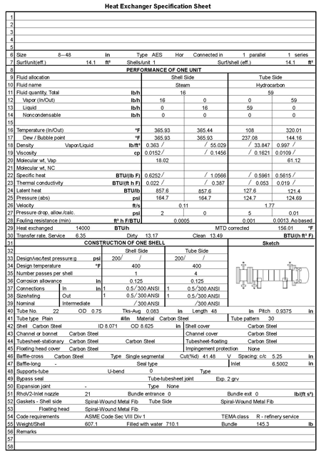
Unitel Technologies uses Aspen Exchanger Design & Rating (EDR) for conducting calculations for the design and specifications of heat transfer equipment. These items, commonly referred to as heat exchangers, include shell and tube type, exchangers, air cooled units, fired heaters, plate exchangers and plate fin exchangers. When needed, the program can also develop a tube sheet layout for specific applications. An example of an EDR is shown below.
Instrument Specification
Instruments are a key component of a modern process. There are numerous instruments that have to be carefully and systematically specified to ensure smooth and safe operation. Some of the more common instruments include:
- temperature sensors
- pressure sensors
- level sensors
- density sensors
- flow sensors, etc.
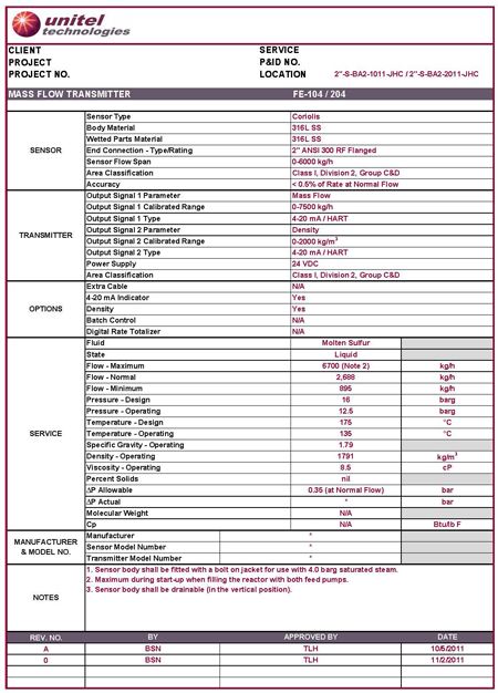
A modern process may have several hundred of these instruments deployed strategically. An example of an instrument specification is shown below.
Control Philosophy
Control System Definition and Specification
Unitel Technologies adopts an agnostic philosophy towards the selection of a control system. We have designed and built turnkey projects using the Emerson Delta V, Honeywell and the Siemens system.
When not otherwise specified by the customer, we often use a control system comprising of an Allen Bradley ControlLogix PLC for process control, two PC based control stations operating Rockwell FactoryTalk View SE control software, and the interface control panel. The basic architecture of the control system is highly functional, very cost-effective, and can be readily adapted to meet both elementary and complex process mission requirements.
The basic architecture is outlined below.
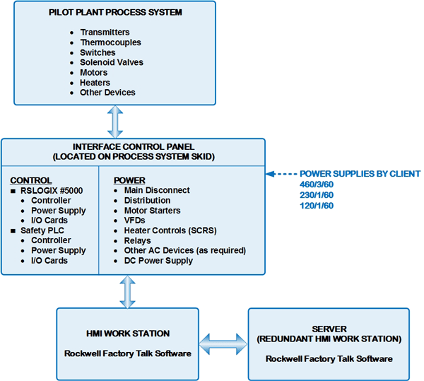
A single interface control panel is used in this system. From a control function perspective, this panel houses the PLC’s power supply and I/O cards. The main PLC carries out the actual control process control function and will continue to operate in the event of a loss of communication to or a shutdown of the HMI work station. The interface control panel receives power at the required voltage from the client’s site
3D and 2D Modeling
Unitel utilizes the Autodesk Plant Design Suite software for all our plant design work; including the following:
- Generation of 2D process flow diagrams and piping and instrumentation diagrams.
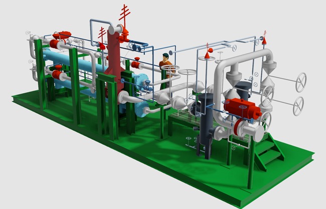
- 3D Plant design including piping design, skid and equipment layouts and structural design.
- Customized process components including pumps, valves, and inline instrumentation created with Autodesk Inventor for better design accuracy and graphical representation.
- Visualization tools including Navisworks and Showcase software.
Pipe Routing
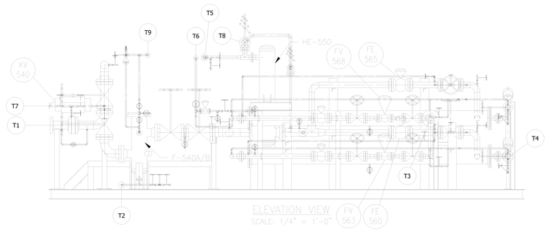
Process and utility pipe routing is a key step in the creative design of a process plant system. 3D pipe modeling is linked to P&ID drawings, which allows for better managed piping layouts. Piping is specification driven, allowing for the creation of isometric and orthographic documentation including automatic bills of materials. An example of a 2D pipe section is shown below.
Preliminary Discipline Engineering
The FEED stage typically requires contributions from other engineering disciplines based on the requirements of the project including:
- Mechanical Engineering
- Piping Design
- Electrical Engineering
- Control Engineering
- Structural Engineering
Preliminary Bills of Materials/Material Take-offs
These BOMs and MTOs are used for developing high quality project cost estimates and developing firm, fixed price quotations for the detailed engineering and fabrication stage of the project.
Preliminary piping material take-offs can be conducted at any stage of the FEED process. This is done by doing preliminary pipe route studies and extracting the material lists from the program. This program is resident within the AutoDesk Plant 3D program.
Cost Engineering – AACE Class 2 Capital Estimates
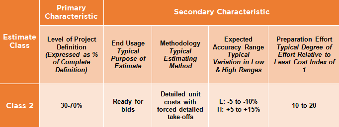
A higher level cost estimate can usually be generated during the FEED phase. Based upon the Association for the Advancement of Cost Engineering (AACE) cost estimate classification system, a typical Class 2 estimate is noted below.
Unitel Technologies employs a number of methods and tools to efficiently develop cost estimates with available data and project information. Our knowledge and history with pilot plants, demo units and other modular systems, combined with our broad process industry experience provides us a rich database to develop cost estimates during an early phase in which the level of detailed information is limited. We use parametric models based on past experience at this accuracy range. We also use equipment factored models employing our in-house major equipment data base and factoring methods combined with ASPEN Cost Estimator.
Unitel Technologies will typically provide a firm, fixed price quotation at the completion of this stage for the execution of detailed engineering and fabrication.
Project Schedule
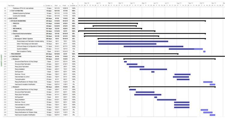
A project schedule is developed during this phase. Unitel Technologies uses MS Project as our standard tool.
A typical project can include 20-200 activities and about 200 total activities. Some of the more complicated equipment intensive projects may contain more than 400 total activities.
